Induction brazing is a process of joining different or the same metals by a filler metal that has a lower melting point than the base materials. Popular joining materials are brass-to-copper, steel-to-copper, copper-to-copper, copper-to-aluminum. The most common brazing materials are copper, zinc, nickel, aluminum, and silver. In induction heating materials are heated rapidly from the electromagnetic field that is created by the alternating current from an induction coil.
A well made brazed joint in many applications will be as strong or stronger than the base metals and the process makes less of part distortion and joint stress. Induction brazing can be used in literally any industry, starting from toolmaking and home appliance industry to oil & refinery, aerospace, and power plant construction.
Image courtesy EFD induction
In this article, we'll tell you about the benefits of using induction heating and simulation software CENOS Platform for induction brazing.
Induction brazing benefits for industrial brazing
Possibility to join a wide range of metals, even ferrous to non-ferrous and simple to complex designs of pipes and other metallic parts.
Selective heating and high reproducibility - the temperature is applied only in defined areas, even narrow ones.
Better joint quality - leak-proof joints due to the high precision of induction heating.
Faster heating cycles - induction heating transfers more energy per square mm than an open flame, this allows brazing more parts per hour than alternatives.
Reduced oxidation and costly cleaning requirements - cost benefits are especially visible when a rapid cool-down cycle is used.
Induction simulation for industrial brazing
Simulation software can predict the exact heating pattern, find errors (wear off, breaking points), save material costs and time on multiple prototyping-testing cycles, plan new or redesign existing mechanical parts.
Primarily for induction brazing, it helps predict material behavior in contact with temperature, so the engineer knows which frequency to choose and what power to apply in reality. In simulation systems, the heat distribution can be seen in visual graphs.
Simulation helps to design both - the coil and the behavior of braze parts. Designing the coil using simulation software is an essential benefit as the coil requires the most time and resources of the production preparation process.
Case study example - electric motor rotor brazing simulation
For brazing, a very precise thermal distribution on the connection must be established. Induction brazing provides this precision, but it is still hard to estimate the precise temperature distribution near the joint, which is needed because the melting points for filler and joint materials usually are very close. This is where simulation comes in – it helps to predict the temperature profile in the joint exactly as precisely as required for the induction brazing system to work.
This example, originally created by Fluxtrol, was simulated in CENOS simulation software, using Fluxtrol Flux concentrator (available in CENOS materials database). It is an induction brazing simulation for a small part of a squirrel cage type rotor (Figure 1) which is the rotating part of the common induction motor.

Making a simulation in the simulation software consists of three easy steps - making geometry, creating mesh and defining physical process application. In this case, the mesh would look like this in CENOS - see Figure 2.

Creating mesh is important, because when the mesh is not small enough within the skin layer, the skin effect might not be predicted accurately.
The mesher used at CENOS software allows to create skin-layers next to the surface in 2D and 3D - figure 2. This feature ensures decent element numbers in the mesh (that decreases calculation time) while ensuring calculation accuracy.
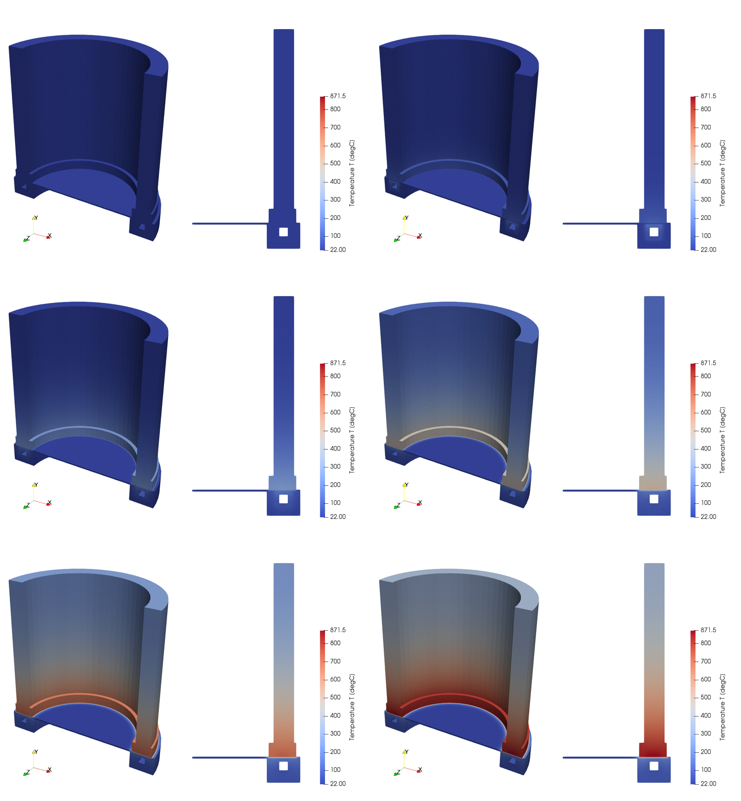
To simplify the simulation a 2D axial-symmetric geometry of the rotor and induction system was chosen. We used the commonly applicable 3 kHz frequency, 50 kW power and a heating time of 205 s - Figure 3.


The goal of this simulation was to determine the temperature in the joint of the copper ring and the rod. Simulation allowed us to find the right parameters to reach the temperature required for proper brazing process. Temperature above 800 degrees Celsius is required to form a high-quality solder connection and the inductor should be excessively cooled in the heating process.
Ask our support engineers (info@cenos-platform.com) more about this case and induction heating simulation application capabilities in the CENOS Platform and get your first simulation test project done within a day! Academic users (teachers, researchers, students) can download a free license and commercial users can get a 10-day free trial here: www.cenos-platform.com


